

For more comments, see my binoscope designer.
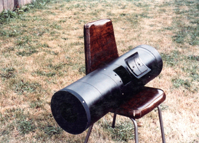
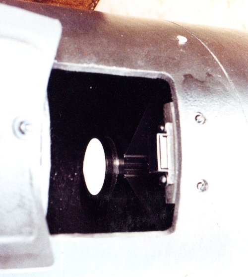
In the lensless Schmidt camera design, coma is eliminated by replacing the Schmidt corrector with an aperture mask at the radius of curvature (twice the focal length), leaving only spherical aberration. Coulter Optical offered kits that included an 8 inch F2 spherical mirror and curved film holder. I built a camera from the kit. THe camera was so fast, collected so much light, that the film holder glowed in the daytime. Later I came into possession of a 2nd 8 inch lensless Schmidt mirror. I decided to turn the two mirrors into a F3 binoscope. The mirrors were wonderfully spherical. Check out the Ronchigram.
Here's a 1959 Sky and Telescope article on the lensless Schmidt camera.
My goal is the fastest speed possible constrained by the size of the secondaries and tertiaries and further constrained by eyepieces that, side by side, will fit our eye's IPD (InterPuppillary Distance). This maximizes etendue (light throughput which is aperture squared * field of view squared).
Dealing with coma:
Critical to the fast binoscope design is a coma corrected eyepiece. My notes on the Houdini 20mm with built-in coma corrector:
Eyepiece study (note that the listed etendue values will be doubled since this is a binoscope)

Field quality at various focal ratios, using my 10.5 inch F2.7:
Conclusions:
The Baader MPCC's performance can be improved by making the primary mirror hyperbolic. See Rob Brown's analysis and his results from making and testing a 5 inch F3.5.
Expected performance (not that a binoscope can be directly compared to a monoscope):
At a 'shoot-out', Robert Asumendi's 8 inch binoscope came close to equalling my 25 inch F2.6 on large extended nebulae like the Veil.
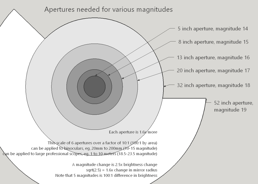
Why 8 inch binoscope? Principally because I have these two 8 inch F2 blanks sitting on the shelf. But also that alignment is easier at lower magnifications and that increasingly large aperture steps need to be taken to gain a magnitude of light.
Contrast with binoculars:
The two mirrors have different thicknesses: 1 1/4 inches and 1 1/8 inches and weight 4 1/2 lbs and 4 lbs respectively. Surprisingly, the two 8 inch mirrors have slightly different sagitta. One mirror has a focal length exactly 16 inches and the other appears faster.
My goal is to slow the mirrors down to F3.5: FL=28 inches; RoC=56 inches.
8F2 sagitta is 0.25 inches, 8F3.5 sagitta is 0.143 inches, a difference of 0.107 inches (2.7 cubic inches of glass to remove).
Sagittal sensitivity: a 0.004 inches change in sagitta = ~0.1 change in focal ratio.


These will be my 8th and 9th fast mirrors. My previous experience with fast mirrors include:

Numerous small chipping at edge: must keep a heavy bevel
Using a diamond ring tool of nearly the same diameter with 60-90 grit; accidentally flattened the edge too much
Switched to a 10.5 inch tool with FL=29 inches (F3.6 for the 8 inch) (TOT (Tool On Top) with strokes that took the mirror just over the tool's edge)
Several hours to finish first mirror
I used the 10.5 inch tool throughout with 60-90 silicon carbide grit
Stopping to bevel frequently both mirrors
Densite with hexagonal tiles. I squeezed the tiles down onto the plastic wrap covering the mirror's face by tightly wrapping the cardboard ring.

The roughly 10.5 inch dia x 30 inch FL tool left the mirrors a little shallow
MOT (Mirror On Top) with 1/3 W strokes
Alternating mirrors every wet
~6 hrs grinding time; edge tiles are half ground down
Mirrors at F3.5

TOT with 1/3 W strokes
Alternating mirrors every wet
~4-5 hrs
TOT with 1/3 W strokes
Alternating mirrors every wet
~3 hrs
TOT with 1/3 W strokes
Alternating mirrors every wet (10 min)
~5 hrs
TOT with 1/3 W strokes
Alternating mirrors every wet (10 min)
~3 hrs
TOT with 1/3 W strokes
Alternating mirrors every wet (10 min)
~2 hrs
The template fits nicely *** but measuring after flash polish shows that the mirrors' sagittae are 0.0014 inches deeper so F3.1 instead of the template's F3.5. The final aluminum oxide finishing powders seems to have shortened the radius of curvature.
You can see the 5 micron shine.


Getting ready to pour the pitch lap on the Densite base (same material I used for the fine grinding tool). I duct tape a cardboard ring so that the ring peels away easily from the pitch by using quick jerking motions.

Pitch is Gugolz #55, shop temp is 60F. I poured the pitch to 5/8 inches thick.
Both mirrors slide smoothly indicating that they have identical curves.
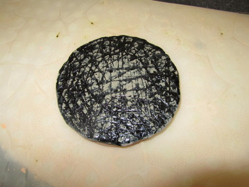
Here the pitch lap is charged with cerium oxide. And showing the mirror on lap.


I mix one part cerium oxide with 10 parts water in a small squeeze bottle. I also have a water spray bottle that I've added a drop of Dawn Dishwashing soap.
My process to begin a polishing session.
MOT with 1/3 COC (Center Over Center) strokes.
10 second video of polishing machine in action. The machine strokes the mirror at half the rate I would by hand.
2 hrs (1 hr per mirror).
Mirrors show even shine from edge to center; no defects such as pits and scratches seen other than haze. Ronchi bands are straight with a 100 lines per inch grating.


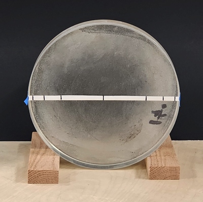
Sagitta measures 0.157 inches (a 5/32 inch drill bit just fits) or F3.1, faster than the F3.5 that I had intended.
Continuing with MOT and 1/3 COC strokes.
5 hrs, swapping mirrors at the halfway mark. Shop temp 50F: stiffer cold pitch better for polishing out.
Both mirrors continue to fit against the pitch lap nicely, indicating that they are at the same radius of curvature.
Looks polished to the eye, laser shows considerable scatter diminishing slightly towards the mirror's center; no surface defects (scratches, pits); straight Ronchi bands, no TDE, no 'stig.
Continuing with MOT and 1/3 COC strokes.
5 hrs with swapping mirrors at the mid-point; shop 50F.
Usiung laser pointer, haze lessening: gone from center, more at the edge. ROC has shortened from 50 1/8 to 50 inches (F3.14 assuming clear diameter of 9.95 inch). Expect final F3.1. Ronchigram: straight bands, no TDE.
Shortening strokes to 1/4 COC, MOT, to bring more polishing action to the mirror's edge. Otherwise as above with shop temp at 50F.
6 hrs swapping mirrors at the mid-point.
Slight haze visible with laser pointer at mirrors' edge. Slightly oblate (anti-parabola).
Returning to 1/3 COC to flatten the oblate curve. MOT. Shop at 50F.
8 hrs swapping mirrors at the mid-point.
Very light sparse haze at extreme edge, visible with the laser pointer. Ronchi bands have straightened.

Continuing with 1/3 COC MOT.
6 hrs, swapping half way through.
Haze gone. Ronchi bands straight. Perhaps a very narrow thin TDE seen way outside ROC (could be grating diffraction)?

Took about a month from start of rough grinding to end of polishing.
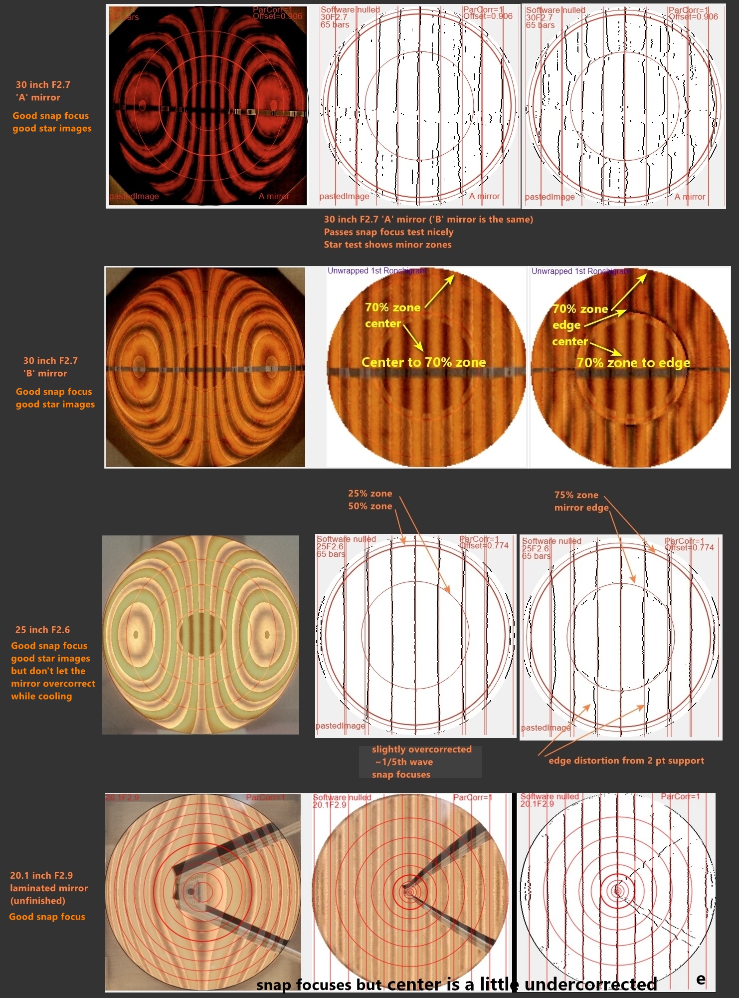
I'll call the slightly thicker heavier mirror 'A' and the other mirror 'B'. The mirrors lost 1/16 inch thickness (approximately equal to the difference between F2 and F3.1 sagittae) so the 'A' mirror is now 1 3/16 inches thick and the 'B' mirror is now 1 1/16 inches thick.
Both mirrors' ROCs are 50 1/8th inches, unchanged from start of polishing. FL=25 1/16 inches and FR=3.13.

Both mirrors' RonchiGrams (RGs) are essentially the same. Note that all RGs are done with a 100 bars per inch grating.


Slight oblateness (anti-parabola) is to be expected after polishing. See my pitch lap calculator.
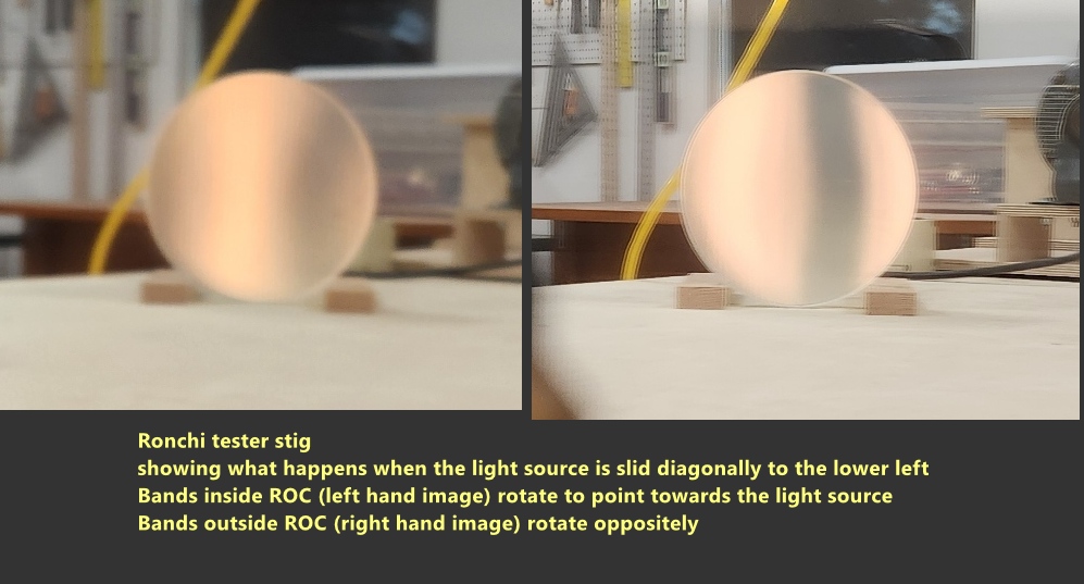
If the light source is offset diagonally from the grating, then the bands twist. Inside ROC they point to the light source, outside they rotate.
Parabolic difference from a sphere is 12 waves.
Both mirrors have the exact same curve in that after pressing the pitch lap with one mirror, the other mirror slides across the lap perfectly.
Whatever I do to one mirror, I will do to the other, in order to keep them matched up.
And I'll use the polishing machine to slowly rotate the face up pitch lap, parabolizing the two mirrors by hand.
Two parabolizing approaches:
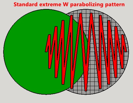
Parabolizing process: I'll use my process that I've developed over a number of fast mirrors. I'll gradually increase the parabolization of the mirror using my lightning quick Ronchi Calc to check overall progress, targeting any zonal issues. I'll use inside ROC Ronchigrams, later switching to outside ROC Ronchigrams as the mirrors' curve improves. Foremost I will keep the mirror's profile smooth. As I come closer I'll use my Ronchi Tape test for quick multi-figuring steps per session. As I near completion, I'll build a star test rig and add the star test to my evaluation. This way I'll finish the mirrors knowing exactly what I'll get at the eyepiece when the mirrors are silvered.
Began parabolizing with extreme W strokes. The water spray bottle has a few drops of Dawn dishwashing soap. I'm using generic or mixed cerium oxide from multiple sources. I use the hot air gun for a minute or two then push the mirror down on the pitch lap for a few seconds.
Initial calibration session #1 of 20 minutes (10 minutes each mirror) to gauge speed and parabolizing approach.
Straightened bands.
Session #2. Long wide Ws. 40 minutes.
Central depression has formed.


Session #3. Narrow Ws to widen the central depression. 1 hr.
Central depression widened. Surprised that I reached close to full parabolization this quickly, dismayed that the central depression hasn't widened to the edge yet to create a nice smooth curve.


Analysis shows high kink at 75% zone measuring ~1.5 waves off; central 25% a tiny bit overcorrected.


Looking outside ROC to better get at what zones are high and what zones are low. Here, the greatest issue is the 75% zone.

Session #4.
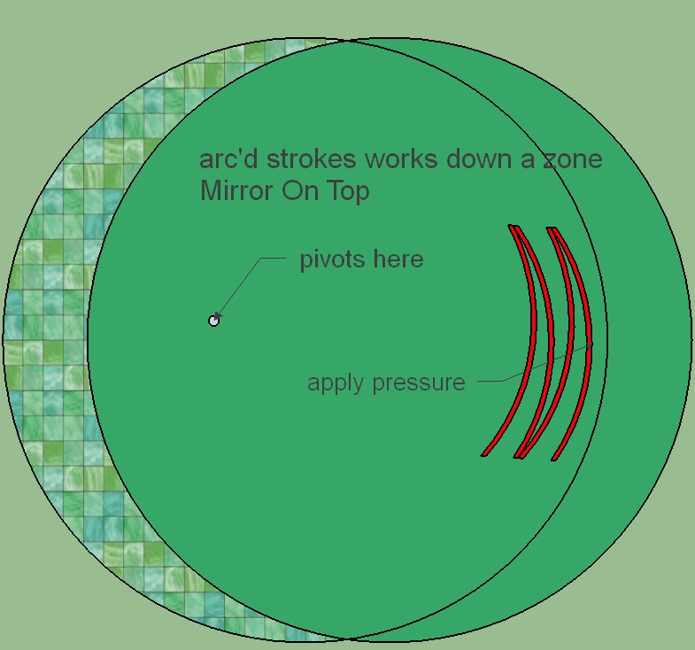
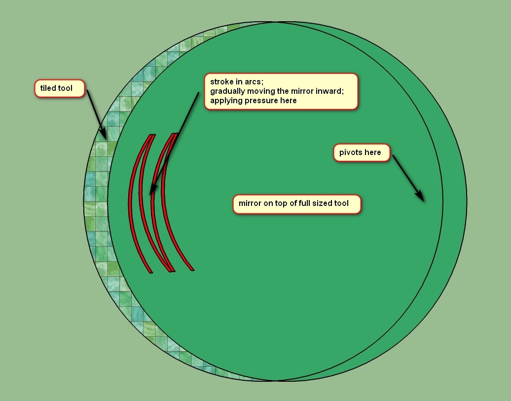
Several ways to fix a high zone.


Both mirror surfaces look defect free.
Session #5.
I switched to the Ronchi Band test, which is lightening quick and requires no analysis, just a glance at the band to mark lineup. I was able to do six sub-sessions of five minutes each in under an hour. See my Ronchi Band Test discussion in my Ronchi Calc.
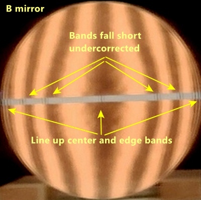
Since the 'B' mirror fell behind, I worked with it, 30 min, with Ronchi Tape Band checks every 5 min.
The bands fall a little short, indicating that the mirror is undercorrected. A quick matchup in the Ronchi Calc software shows about 90% corrected. Acceptable correction is 97% to 103%. The 'A' mirror looks similar.
Sadly, I also roughed up the surface. Contact was not perfect at first. I would do well to remember my rule, namely, to only work a session when motion is silky smooth with even resistance.
Overall, I did improve the 'B' mirror to match closely the 'A' mirror.
Session #6.
Working on the 'B' mirror. 45 minutes with quick Ronchi Tape checks every few minutes as warranted. Extreme W strokes with accentuated pressure at times over the lap's edge.
Radius of curvature is exactly 50 inches.
Much closer - the 'B' mirror is caught up to, if not slightly better, than the 'A' mirror - see the analysis - the 75% zone needs a touch more polishing.


Session #7.
Continuing with the 'B' mirror. My goal is to get the mirror close enough to justify a star test. Main defect is the high 75% zone.
30 min with checks every few minutes. Extreme W strokes along with arc strokes with accentuated pressure.
A hint undercorrected overall and at the extreme edge.

Session #8.
Improve the 'A' mirror so that it's ready for star testing.
Here's the starting Ronchigram analysis. As you can see, the mirror is undercorrected. Best fit parabolic correction is ~80%. Very close to the 'B' mirror at the start of session #6. Sessions #6 and #7 on the 'B' mirror comprised 1 hr 15 min of parabolizing time.

Way over parabolized in the first 15 minutes (120%); spent the next 15 minutes bringing the mirror back. 30 min total. Shop temp 60F. I warmed the pitch too much, softening it, so that the extreme W strokes caused the lap's edge to sink, losing contact there, causing over parabolization. I then used arc'd strokes accentuating pressure on the mirror's edge over the lap, to reduce parabolization.

Session #9.
Reduce the remaining over parabolization in the 'A' mirror.
4 min of arc'd strokes really flattened the mirror, reducing correction to 70% or so. At least the curve is smooth. Multiple sub-sessions of approx 5 minutes each of extreme Ws brought back almost full correction. The 80% zone is lagging (high) just a tad. 56 min.

Session #10.
A mirror: lower the 80% zone. Which I did, but in the process I dug a low 50% zone. So after largely fixing that, I'm here. 47 min broken into 3-5 min quick sub-sessions.

Took two weeks to parabolize both mirrors.
10 sessions between the two mirrors; 6 hrs 40 min total time for both mirrors.
Going into star testing, the 'A' mirror's 50% zone tests ever so slightly overcorrected (approx 1/20 wave, 0.5 M-L), the 'B' mirror tests nicely.
The mirrors:
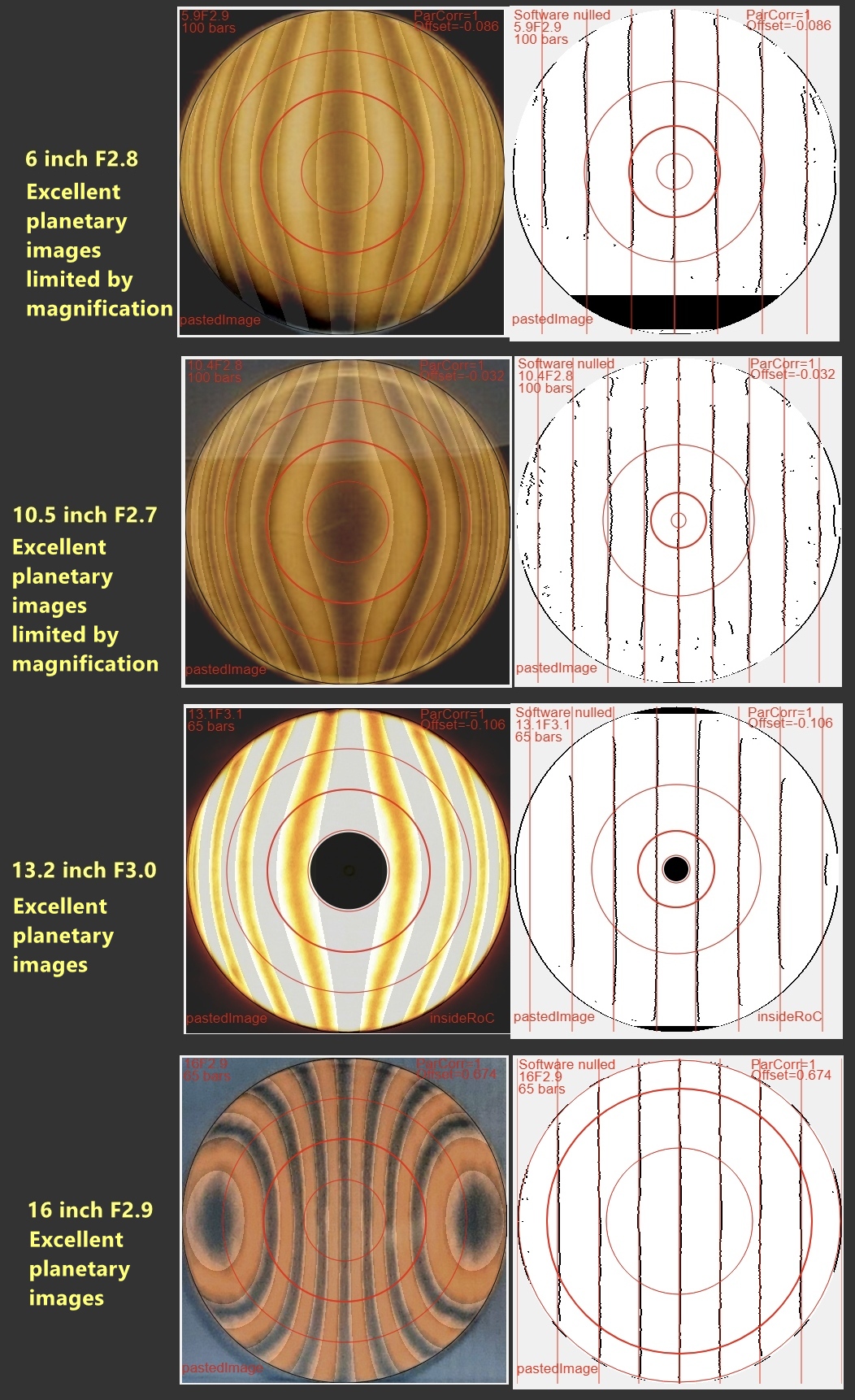
For comparision, the finished Ronchigrams for my 6 inch F2.8, 10.5 inch F2.7, 13 inch F3.0 and 16 inch F2.9 mirrors. You can see that the 6 and 10.5 inch mirrors, tested with a 100 bars per inch grating, show slight deviations from straight. The 13.2 and 16 inchs tested with a coarser (but necessary because of the extreme parabolic deviation from spherical) show perfectly straight lines. The two 8 inch mirrors compare favorably to the 6 and 10.5 inch mirrors.
And comparing to my large thin fast Mirrors


In a month and a half, I ground, polished and parabolized both mirrors to matching focal lengths.
Design criteria to consider (from my binoscope designer):
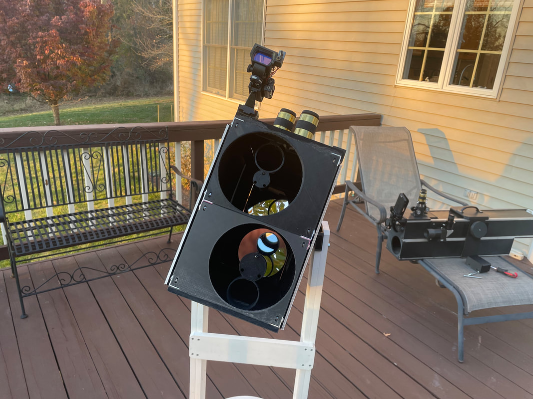
Here's my 8 inch [20cm] F3.1 binoscope
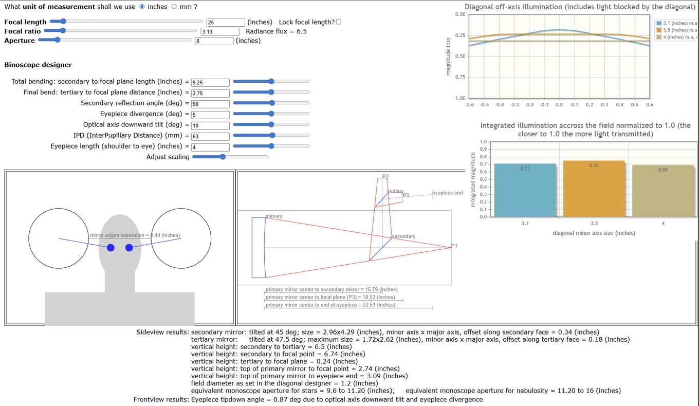
I'm interested in exploring an idea proposed by Clive Milne, namely diverging eyepieces. Advantages include a closer IPD for a given pair of eyepieces and a more comfortable fit especially regarding our noses. Holding eyepieces to my eyes while facing a blank wall suggests an optimal diverging angle of several degrees. I can shrink the IPD to 54mm if Houdini 20mm eyepieces are set to a 7 degree diverging angle per eyepiece. It seems prudent to explore diverging angles up to 10 degrees per eyepiece. According to my binoscope designer, the primary mirror separation will vary from 7.28 to 8.24 inches, about an inch change. However, adding the length of the eyepieces will increase the primary mirror separation variation.
An intriguing new design is the floating tube concept for IPD and merge adjustment by Jonathan Pogson, coupled with the divergent eyepieces concept inspired by Clive Milne. Note that Jonathan's graphic is for a fixed eyepiece divergence angle and that the pivot is above the optical tube assembly's centerline.

Investigating two eyepiece divergence angles and two IPD widths with a constant central pivot of each optical tube assembly leads to four situations:
My software calculates that the primary mirror separation varies from 6.9 to 8.4 inches, or a change of 1.5 inches. This comes from the IPD variation and from the focal point's tilting outward due to the eyepiece divergence angle. But that's not all: the outward tilt due to the length of the eyepiece needs to be added. An eyepiece that's 4 inches long (bottom of shoulder to eye position) at an eyepiece divergence angle of 10 deg tilts from the center line by 0.7 inches. Since there are two eyepieces, the separation between the mirrors can increase by up to 1.4 inches. So the actual primary mirror separation for these four situations varies from 6.9 to 9.8 inches, a difference of 2.9 inches.
Achieving these four situations by rotating the optical tube assemblies requires rotation angles from 0-36 degrees. A larger diameter binoscope or a slower focal ratio binoscope would require significantly less rotational change, as would setting the eyepiece divergence to a constant value.

An external hinge point (above or below the twin OTAs) shrinks the required rotation of the OTAs to 8 degrees in order to accomodate the four situations that I list above. The altitude bearing points change their angles and spacing. And in order to merge, the OTAs have to change their pointing angle depending on eyepiece divergence and magnification. About an 1/8 inch change is needed. Here, I'm using a 'V' shaped merge idea inspired by the Bonanza Beechcraft's 'V' tail, an idea that Jonathan Pogson has also independently proposed.

Various schemes include linkages like scissor lifts and precision guide rails.
Something like this...

The tertiary mirror's pointing angle needs to change at half the eyepiece divergence angle. Here's my scheme, inspired by an exchange of ideas with Jonathan Pogson.
![]()
Secondary size is 3.1 inches minor axis and tertiary size is 1.83 inches minor axis.
Frank Szczepanski uses a sled to adjust the IPD.

Here's a study showing how far a sled with an angled eyepiece travels when changing the IPD.

The eyepieces need baffling so that they do not see a ghost image from the other mirror. Here's how Frank Szczepanski baffled one of his side-by-side binoscopes.

Peter Tinkerer angles the eyepieces like Frank Szczepanski and tips the two tube assemblies so that his head doesn't tilt too badly.
Here's his webpage with several side-by-side designs.
For focusing I can use friction-twist or Pierre Lemay's helical Crayford. I can take advantage of the eyepiece barrel's shadow when placing the friction and Crayford pieces.

Besides the 'V's spider design that I've used before, here are some ideas for a sled focuser that would hold both diagonals and the eyepiece. This to minimize the eyepiece to tertiary distance.


What I like most and least of each design.
Like most
Like least
Like most
Like least